
Bullet2 is an AP/Bridge build around Atheros AR2316 SoC. Its CPU is based on MIPS 4Kc technology with a clock speed of 180MHz. It also features wireless and 10/100 Ethernet MAC.

The device comes in a simple black box. There aren’t any documents contained in the box e.g. users’ manual. All directions and information are written on the box.

Its size is much bigger than someone would expect. According to manufacturer specs, the casing is made of UV stabilized plastic and is suitable for outdoor use. Although it seems that all of the casing is made of ABS material, the LED window is covered by some other kind of plastic. This may be a point of weakness for the weather proofing properties of the device.

The Ethernet port is protected by a plastic screw cap. There is a very thin rubber gasket at the end of the outer thread for waterproofing, but it can easily get ruined if you tighten the cap too much.

Next to the Ethernet port is the reset button. The maximum supply voltage of 24VDC is also indicated. Bullet2 is powered exclusively through POE.

The entrance of the ethernet cable is protected by a rubber cable gland. There is a cut (see photo) to help the cable pass through the hole. It doesn’t seem to provide reliable waterproofing.
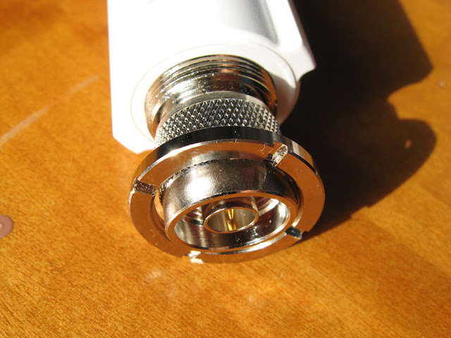
Bullet2 PCB is released from the casing by unscrewing the nut behind the N-type connector. This nut is the only way of fastening the PCB to the casing and it features a special gasket which provides good waterproofing.

Since the nut is unscrewed, the PCB can be removed freely from the other end. The PCB slides in/out onto special cuts on the inside of the casing.

There are at least two PCB layers. On the soldering side there is the 10/100 Base-TX physical layer transceiver, the Flash memory and the LEDs. KSZ8721B 10/100 Base-TX has on-chip filtering and very low power consumption. M25P32 Flash memory size is 32Mbit (4ΜΒ) and guarantees 100,000 erase/program cycles per sector.

On the component side there is the SDRAM, the 10/100 base-T transformer, the voltage regulator and AR2316 SOC. ICS42S16800 SDRAM size is 128Mbit (16MB) with clock speed at 133MHz. The 10/100 base-T transformer is H16125MCG. The voltage regulator is AOZ1210AI with an efficiency up to 95% and input voltage range from 4.5V to 27V.

As you open the metal shielding, AR2316 SoC can be accessed. There is a window for the heatsink on the metal shielding to better cool the IC.

There is a sticky heatsink on AR2316 SOC to keep it cool

It looks like the serial pinheader is hand-soldered…

LEDs are in plastic cells which guide light to each indicator window on the casing.

To connect to Bullet2 via serial we need a TTL to RS-232 interface
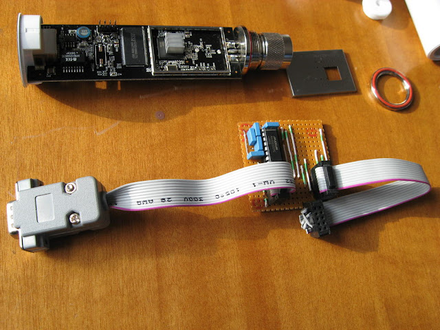
Supply voltage is 3.3V so we need some IC which can operate there e.g. MAX3232. The supply voltage for the interface is provided by Bullet2 itself.

The length of the cable between Bullet2 and the interface should be as short as possible.
We can access RedBoot bootloader via serial console and do several tasks on Flash memory and SDRAM like e.g. try a custom firmware without flashing it, revive a bricked Bullet2, etc.


0 comments:
Post a Comment